eTrigger is an innovative system that allows the continuous monitoring of the encoder state and produce a trigger output at the exact encoder positions. Up to 4 separate encoder positions may be used for triggering purposes.
It's a perfect solution for an automatic control of industrial and commercial machine vision applications. High speed communication is the key for a flexibility and efficiency. The ability of “on the fly” injections, gives the opportunity to reach the optimal performance and save your time for trigger configuration.
The build-in processor is used to calculate not only the status of the encoder, but also the trigger point in advance*, depending on velocity of the motor. The Hardware supports up to 1000 KHz Encoder Frequency.
Typical Applications:
- Time efficient industrial and commercial applications
- Vision solutions / camera trigger
- Motion control applications
Features:
- Up to 4 Programmable triggers
- 4 maskable output channels for each trigger
- Selectable movement direction (forwards, backwards or both) for each trigger
- Ability to store the configuration into Flash ROM
- Support for high-speed encoders with operating frequency up to 1000KHz
- Realtime trigger position calculation depending on current motor speed
- Ethernet/UDP and RS232 communication interfaces
- Configurable trigger duration
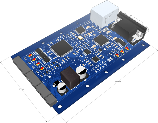
Mechanical & Electrical Specifications and Pinouts:| eTrigger Dimensions & Pinout | Schematic wiring of the channel output connectors |
|---|
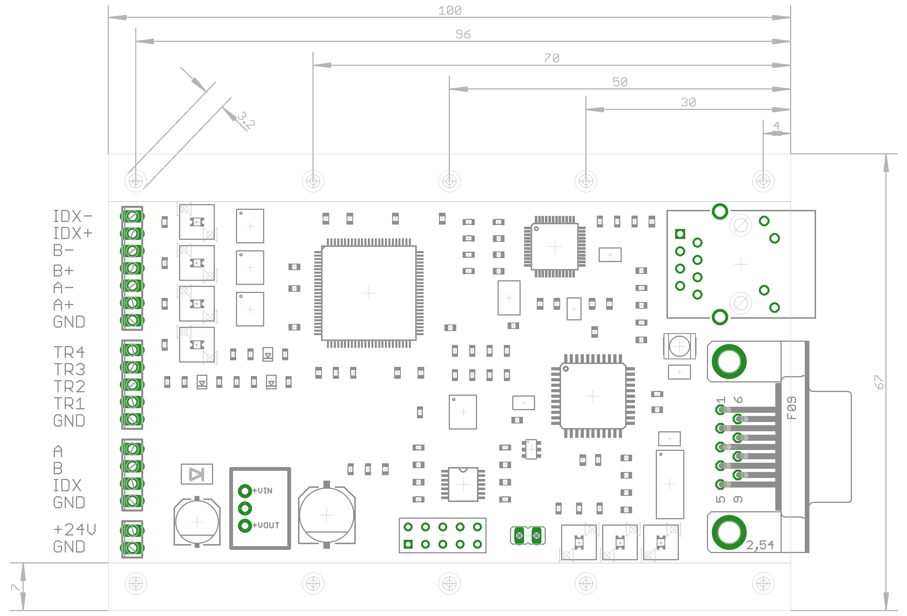 |  |
RS232 Pinout:| DE-9 pin | Signal Name | Description | Direction |
|---|
| 3 | RX | Data Receive | IN |
| 2 | TX | Data Transmit | OUT |
| 5 | GND | Signal ground | |
Channel Outputs:| Signal Name | Description | Direction | Voltage |
|---|
| TR1, TR2, TR3, TR4 (Channel 1....4) | Channel output | OUT | min: VDD-1V |
| GND | Channel ground | | GND |
Encoder Pinout:| Signal Name | Description | Direction | Voltage |
|---|
| A- | Encoder Phase A- | IN | -7...+12V |
| A+ | Encoder Phase A+ | IN | -7...+12V |
| B- | Encoder Phase B- | IN | -7...+12V |
| B+ | Encoder Phase B+ | IN | -7...+12V |
| INDEX- | Encoder Phase INDEX- | IN | -7...+12V |
| INDEX+ | Encoder Phase INDEX+ | IN | -7...+12V |
| GND | Encoder Ground | | GND |
TTL Encoder Pinout:| Signal Name | Description | Direction | Voltage |
|---|
| A | TTL Encoder Phase A | IN | 0...+5V |
| B | TTL Encoder Phase B | IN | 0...+5V |
| INDEX | TTL Encoder INDEX | IN | 0...+5V |
| GND | TTL Encoder Ground | | GND |
Power Supply:| Signal Name | Description | Voltage |
|---|
| VDD | Power supply | +9...+36V |
| GND | Ground | GND |
Summary:| Supply voltage (VDD) | +9....+36 V |
| Encoder input voltage (A±, B±, INDEX±) | -7...+12 V |
| TTL Encoder input voltage (A±, B±, INDEX±) | 0...+5 V |
| Trigger channels output voltage | min: (VDD-1V) |
| Ethernet communication speed | 100 Mbps |
| RS232 | 115200 bps, 8 bit, 1 stopbit, no-parity |
| Max trigger reaction time | 10 μs (100 KHz) |
| Max encoder frequency | up to 1000 Khz |